
I also discovered that purchasing a new (after market) rudder results in a significant financial penalty for no better securing it, so I decided to build my own. This article, I hope, anyone in the same boat (forgive the pun) as me, will provide guidance and simplifying the project of building your own.
Nothing I did during the construction is a cast in stone method, and I encourage you to vary the design to best fit your personal requirement.
Materials List:
Rudder Blade: 3/16 aluminium – Approx Size 2’X 4’ (this will give you scrap for other projects). This was not as easy to find as I thought, but I found mine at a scrap yard, it had been painted and looked pretty rough, but was perfectly flat and just needed a little sanding and polishing.
 |
| Scrap 3/16 Aluminium - after blade was cut out |
Pintles: these are BUGGERS… pintles are not just pintles, there are a large variety of sizes, bot pin and bracket. After ordering the incorrect size, I had to scour the internet and ship (and a crazy cost) from the central US. My size (yours may be different so check carefully) was a 3/8” pin with 1 ½ width (finished rudder width) and 3” long mounting bracket. There are 3 pin sizes available. 8 mm, 3/8” and 1/2”. Carefully measure the hole size in your gudgeon before ordering. The 1 ½” width will fit my construction identified below. If you can, order the set with one having a long pin, the other with a normal pin.. this helps when putting the rudder on every time. UPDATE: Just found a great vendor for these odd sized pintles check them out: http://www.duckworksbbs.com/hardware/p-g/index.htm

Plywood: (for rudder head):
- 4’X4’ sheet of good one side 5/8 plywood
- 4’X4’ sheet of 3/8 plywood
Hardwood: (for handle):
2” X 6” X 6’ birch or ash (I used birch)
 |
| Kinda Before and After photo. |
Scrap wood: (for prototype)
- 4’ X 8’ cheap wood, could be ¼ ply, or press board - I used some old 1/8 in wall board.
 |
| Just old wall board that I had laying around... easy to work with. |
Hardware: (buy extra)
- 6 - 1/4 “ X 2” stainless steel bolts, 12 washers, and 6 lock nuts (with plastic in the threads)
- 1 - 1/4 “ X 2 1/2” stainless steel bolts, 2 washers, and wingnut
- 1 – 5/16 X 2” stainless steel bolt, lock nut and 2 large washers
Aluminium: for head –
- 12” X 12” 1/8 aluminium
 |
| Aluminium for head, also rope, cleat (as detailed below) |
Rope, cleat, O-ring: I will leave the sized to you as I don’t recall what they were when I bought them, but you will see from photos the purpose (pulling up blade and securing it)
Epoxy (and hardener)
Marine wood glue
Clear varnish (you may wish to stain also, I was too lazy)
Tools:
- Work bench
- Jigsaw (and a LOT of blades
- Drill (with a LOT of bits)
- Socket set
- Hand Planer
- Sander with 60 grit, 80 grit, 120 grit, 400 grit
- C – clamps – 6 or so would be nice
- Angle grinder with general purpose wheel
- Hand Saw
- Metal File
- Drill Press would be ideal (I did not have one)
- Hammer
- Protracter
- Straight edge
- Measuring tape
- Eye protection – this is a MUST, trust me, fishing aluminum bits out of your eye is not fun - I know this as fact.
- Band Aids
- 40oz of Amber Rum, Mix and Ice cubes.
Construction:
Step 1:
Using the rough plans here, I drew out the blade on the scrap wall board I was using.. . I added 3” to the length of the rudder from these plans. Just my choice to do so, you can do as you feel best.
 |
| This is the best quality picture of the original Tanzer 16 design I could locate - some guessing involved on certain measurements and specification -there are 2 bladed designs, I chose the lower of the 2 illustrated. |
As the finished head will be constructed of 3 sandwiched pieces.. the 2 outer pieces are 5/8 in ply, and the center - I am calling the stopper, is of 3/8 ply.
The Blade is 12” across, and I set the protractor at 5” to give me the curve at the top (10” diameter). Mark the center of the arc as you will need to drill a hole there shortly.
Step#2
Sketch out the shape of the head of the rudder, I used the limited information on the plans, and eyeballed the rest.
Step #3
Cut out the rudder shape, and lay it onto your sketch of the head to make sure the back angle of the head is the same as the angle of the rudder when it will be in its full down position. This is form over function, but it will look better as the head makes a smooth transition to the angled rudder.
 |
| I unfortunately did not photography this rather important step.. but the above cut out of the head prototype should offer insight as to the purpose of shaping the parts of the rudder head (and blade) |
Step #4
Drill a 5/16 hole in the rudder where you marked from the arc that was drawn.
Step#5
Once you are happy with the shape of the head, cut 3 of these out of your scrap.
With one of them, realign the rudder into the correct position on it an and trace the shape of the rudder on it (the curve, the 2” step etc. This piece will be the “stopper” or sandwiched 3/8 ply. Also, pivot the rudder to the “up” position and trace that on your cutout.
Cut this piece along the traced lines and the outer lines. And cut the remaining 2 pieces of the head (the pictures show better what I am rambling about. (refer to photo above to the finished product of this step)
Use the rudder drill hole to determine the pivot hole location on the 2 head pieces and drill em out.
Step #6
NOW is time to assemble.. it is self-explanatory how this all fits together, you can put your 5/16 bolt to hold the rudder to the head, and drill a few smaller holes and temporarily bolt the 3 parts of the head together. You “should” have a pretty good template of what you want the finished product will look like.
 |
| Assembled prototype (bolts other than the pivot hole are simply for prototype, NOT for finished rudder) |
Step #7
Once you are happy with the rudder position in the down, and up position.. you are ready for the next step. Place you pintles in the gudgeons on your boat, align the top of the head of the rudder prototype. I used a straight edge to make sure the top of the stern and the top of the rudder were perfectly aligned. Now you can make the drill mounting holes for the pintles on your mock up.
 |
| This is the finished product being measured (double checked for pintle placement - but was done (not photographed) with the mock up. |
IMPORTANT – make sure the mounting holes (and future bolts) for the bottom pintles do not interfere with the free movement of the rudder. (it will be close)
Step #8
Once you have made all of the final adjustments on the mock up, and you are pleased with the look and the workings, now the fun begins. (the hard part is over).
Disassemble the prototype, and trace the rudder, onto your sheet of 3/16 aluminium. The left and right head onto the 5/8 plywood – MAKE SURE the “good” side of the plywood will be facing out. And trace the “stopper” piece onto the 3/8 ply.
I allowed a little extra on all of my tracings to allow for sanding, or grinding.
Step #9
Cutting the aluminum is well, a chore. I did burn up one jigsaw (needed replacing anyway) and went through several blades.. but be patient, use a med tooth wide blade, but feel free to experiment with different teeth (fine, med, heavy). Clamp a straight edge on the aluminum that the jigsaw can butt up against (on the side) to help in keeping your cuts as straight as possible. I am far from a safety nut, but safety glasses are highly recommended for this.. or you can prefer to use a mirror and eyewash solution, and enjoy scratched eyeballs – your call on this one. I tried both, and prefer the first option.
 |
| Finished Aluminium blade, beside the scrap wood prototype. |
After the aluminium is cut, use the angle grinder to fix any cutting flaws and neaten the edges and round them. Fine tuning with a file is a nice touch.
If you are using scrap aluminium from a recycler company, you may have to sand the rudder blade, starting with 80 grit, and finishing with 400 grit.
Using the scrap metal template as a guide, mark and drill the 5/16th hole for the pivot point.
Step #10
Now back to the head of the rudder… time to cut your traced 5/8 and 3/8 plywood. AGAIN, a reminder, this is a good time to double check that the “good one side 5/8 ply” has the good side facing outward.
With the pieces cut out - examine both sides of the 3/8 ply and the insider facing sides of the 5/8ths ply.. if there are any deep knot holes, or any holes that will not be eliminated by a quick sanding follow the following step. Sand only with 120 grit the inner facing 5/8 and both sides of the 3/8 - this does not have to be extremely smooth and actually a little texture is a good thing to help the glue adhere (a later step)
 |
| Tracing the 5/8" ply from the parts of the mock up |
 |
| This jig saw now longer exists.. caught fire on the aluminium cutting.. Farewell old friend. I used a hand saw for the straight edges and the jigsaw only for the curves areas - made for a cleaner finish. |
Step#10A (optional)
As the rudder will be getting wet frequently, it is best to eliminate any holes on the insides of the head that will hold water and cause rot. Mix up a small batch of epoxy and hardener. Now mix in fine sawdust with the epoxy mix - thoroughly - until it reaches the consistency of peanut butter - use this "paste" to fill any holes on the inner parts of the plywood assembly. Let dry for 4 hours or so. Then this can be sanded smooth.
Step #11
Using the mock up, mark the blade pivot hole (5/16th) to the outer head (one side only), and drill one side. Carefully align the 3 parts of the head, so the edges align as close as possible (sanding and finishing will be done later). Clamp the components together (protecting the wood with shims. Transfer the pintle mounting holes, from the mock up.. and dry fit on stern of your boat to confirm. Then dry fit again.. and again.
 |
| Clamped for the various dry fitting efforts and drilling mounting holes. |
 |
| Another Angle |
Step#12
Using a drill press or a very steady hand drill 1/4" holes for the pintle mounting bolts and using the one 5/16 hole for a guide, drill through the other side of the rudder head for the blade pivot bolt. Do not remove clamps yet.
Step #13
Handle mounting component. With a piece of cardboard, mock up the correct size for the 1/8" aluminium handle mount. The width should match the width of the top of teh rudder head (mine was 8 1/2 inches) and should allow at least 2" down on either side of the rudder head for bolting. Mine extended 3" high above the head of the rudder head. This allowed my handle (where it slips in to the mounting component to be 1 1/2 wide (the width of the rudder X 3" high).
After the cardboard mock-up is perfect, trace size and bend points onto the 1/8" aluminium sheet. With a jigsaw, cut the aluminium to size.
 |
| I don't have any photos of the bending and forming of the metal handle holder as it was a frustrating process and I was too mad to take pictures.. but this is the end result. (note the notches around the pintles, and that the handle pivot hole is not drilled yet) |
Step #14
Place a scrap piece of 2' X 10" lumber, vertical in your work bench. This is a lot of guess work, but clamp the cut piece of aluminium to it. Clamp it firmly, Bend it over the top of the butt of the 2X10 to form the desired shape. (You will have to play with this). Dry fit and make any adjustments required.
On a drill press, and the aluminium placed on the clamped together rudder head, drill 2 mounting holes (see below photo) - DO NOT drill handle pivot hole yet.
 |
| The design of this is your choice, I chose to cut out notches for where the pintles will be fixed to the rudder. Rounded the other side for cosmetics only. The 2 mounting holes can be drilled at this step - BUT the handle pivot hole must be done later. |
Status Check - we have the rudder cut, shaped and polished. We have the head clamped together with the holes drilled for the blade mounting, 4 holes for the pintle mounting, and 2 holes for the handle mount. With the head still clamped, insert and temporarily bolt in the blade.. Test the movement, and the stops. Full down position and full up position.. This is the last chance you will have to alter the shape of the 3/8 inner stopper ply.
Step#14
Unclamp the head, using the 3/8 ply stopper as a guide trace the edges on the inside of either side of the 5/8 ply. The object it to apply varnish to the parts of the head that will be exposed to water and NOT on the areas were it will all be glued together. Tape off the areas that will receive glue. Brush on varnish to the exposed areas (and the edges of teh 3/8 stopper). After the varnish dries, lightly sand with 120 grit, and repeat this process 8 times. See photo below.
 |
| taped off area for varnish.. do not varnish areas that will be glued. |
 |
| NOTE!! You will see here how close the lower pintle mounting holes are to the edge of the stopper and the blade of the rudder. Be careful with your design that this is not an issue. (its easy to overlook) |
Using marine wood glue, apply to both sides of the 3/8 ply and sandwich the outer (5/8) parts to it. Using the 1/4" X 2 stainless bolts and washers, bolt the 3 parts together. Also apply clamps where possible.. It is important that all of the edges are tight, as when finished we want these edges to be water proof. Let dry for 24 hours.
Step #16
Remove all of the bolts - now is the time to make it all pretty.. Starting with 80 grit power sander (or 60 depending on how much tweaking needs to be done) snad the sides of teh rudder head so all 3 pieces of plywood appear as one piece. Sand the faces of the head and round the edges to your preference. Change to 120, then 400 for final sanding.
Step #17
Varnish (or stain, then varnish) the head, sand between coats - I suggest 8 coats, but again, that is your discretion. Let dry thoroughly
Step #18
Fasten the pintles, the handle mount (aluminium) and the blade and mount on your Tanzer. With a scrap piece of lumber, or broom handle or similar, determine your desired length of your handle. Test extended fully in each direction and your preferred seating area (an extender will be discussed later). Measure and record the length you prefer - allow 2 inches longer for final detail work and trimming.
Step #19
This is where you get creative with the desired shape of your handle, I googled, experimented to some up with the shape of mine.. Just remember that it has to come under the boom pully mount, and over the edge of the cockpit, so I put a small bend in mine.
Depending on what wood you have, determines how you will cut your handle out. I had a cut of birch, that was 1 1/2 in wide. I cut much wider that I wanted my finished size.
With a power saw, a hand planer, and 60 grit sandpaper and the help of my son worked down to a shape and size that I liked.
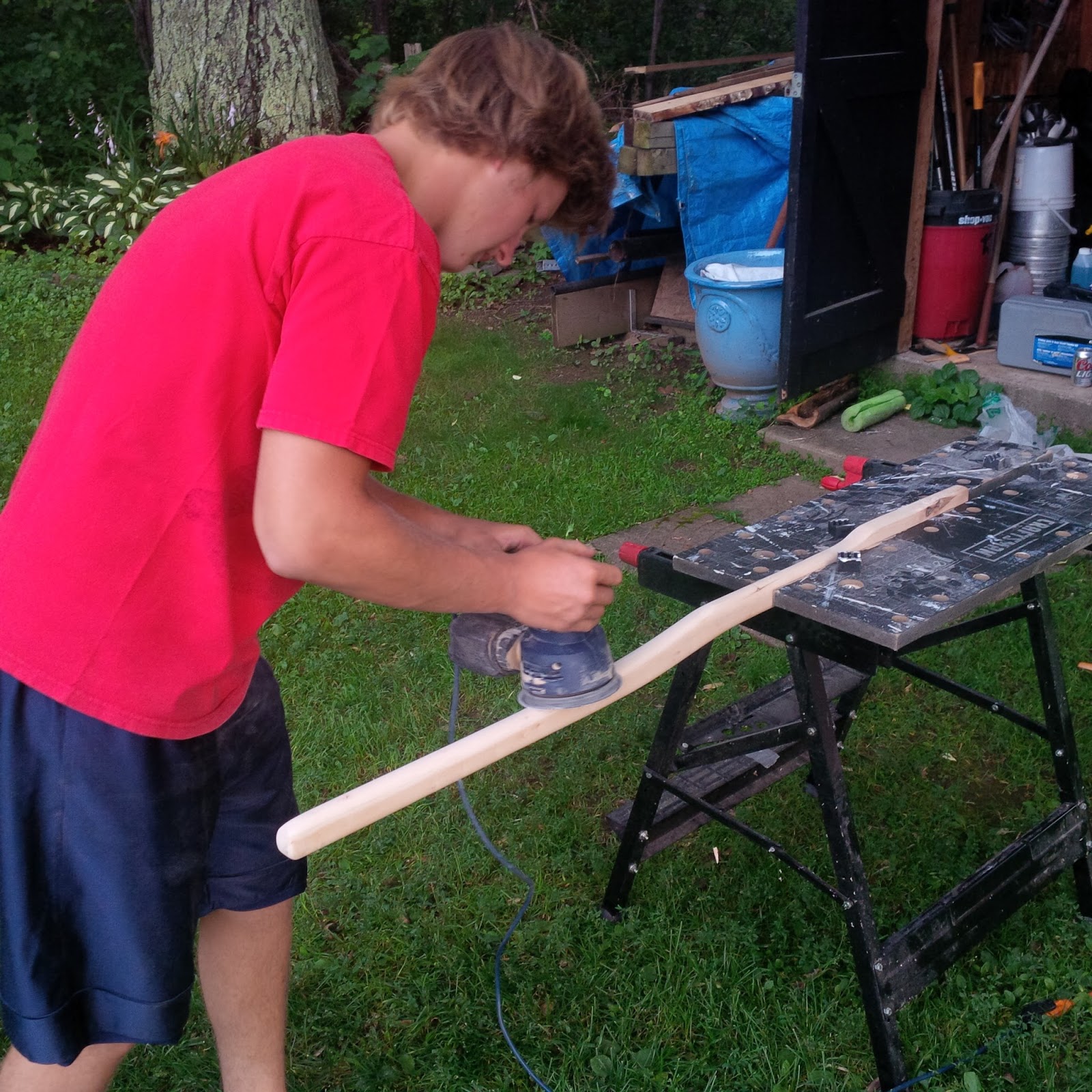 |
| Having a 19 year old son makes this task much more tolerable |
 |
| Before and After |
 |
| Finished (note the curved end to keep from binding when rotated slightly upward |
 |
| Laminated to widen |
Step #20
Place the handle into the head of the rudder.. this is a bit finicky, but determine where you want the handle to pivot - you can see from my photos that I have it roughly one inch from the end of the handle. With the handle in the exact desired placement - drill a 1/4 inch hole through the aluminium, and the handle. take care to do this as perpendicular as possible.
Remove handle and with a protractor, draw a curve using the hole as an apex, to trim an arc in the handle end to keep it from binding when it is raised (it will only raise to the top of teh front of the aluminium mounting bracket - and if thought out well enough it will keep it from hitting the pulley mount at the stern of the sail boat.
Step#21
As done with the head of the rudder, varnish with 8 coats (or stain if desired)
Step #22
Attach the handle to the Rudder with 1/4" X 2 1/2 stainless steel nut and wingnut.
Step #23
GO SAILING!!!


ODDS AND ENDS...
- I built a small aluminium guide and riveted it to the top of the handle mount - I am not that pleased with this design, and will probably be reworking it. The cleat on the handle can be placed to fit best your personal design of the handle, as long as it is free from the pulley mounts and the extension
- To accept an extension, simply drill a 1/4 vertical hole in the end of the rudder handle
- The pintles I purchased bound against the boat when turned fully - so I was required to grind and file to eliminate this.
- I will be drilling a hole in the lower pintle to accept a cotter pin or ring to completely eliminate the possibility of my needing to build another.. I find the stock retaining system unacceptable and clearly unreliable.
UPDATED: Found a great blog that has lots of Tanzer 16 repairs/upgrates etc.
- http://jimslittleboat.blogspot.ca/ Jim also has the holy grail for all Tanzer 16 owners, the full blueprint page - which I am excited to now have added below....


Nice work!
ReplyDeleteMine (#379) has a hole in the upper pintle for a split ring retainer. So far I haven't gone over, but hopefully it will hold.
Paul - I scoured the earth to find 3/8 diam pintles with a hole for a retainer.. but could not locate any (actually 3/8" pintles are a rare breed themselves) - so as soon as I get access to a good drill press, I will have a retaining hole in mine as well. Thanks for reading and commenting.
DeleteHi Darryl, Great work on the new rudder. What a coincidence - we have a Tanzer 16 too and were driving back through your part of New Brunswick on our way back to Ontario on the very week you posted this. Btw there is an ad on kijiji in Ontario for a guy selling a rough but complete Tanzer 16 in Meaford Ontario for $250. I went to look at it and made an offer on all the bits (mast, boom, sails, rudder, centreboard etc) without the hull but he only wants the whole thing gone. I don't really NEED anything so I didn't bite but who knows, I may change my mind. Take care, Phil
ReplyDeleteThanks for dropping in for a read.. It would be hard to walk away from the old tanzer you looked at.. considering when I was looking for a few parts for mine you could easily make a few $$ just selling off the pieces. As I started researching how to build my rudder (with no good info available thus this blog post) I did find a few articles about repairing hulls etc... would be a fun project to resurrect the $250 boat. I did many other repairs (rails, keel etc) and I quite enjoyed being covered in fibreglass, epoxy and paint for a few weeks. I may someday put up a blog on some of the other work I have done on mine.
DeleteThis is a very helpful and informative guide.
ReplyDelete